Block Diagram, Control System Analysis, Transfer function

Mass-spring-damper rotational system. Problems solved. Catalog 3

The transfer function of a rotational Mass-Spring-Damper System. 

In this PDF guide, the Transfer Function of the exercises that are most commonly used in the mass-spring-damper system classes that are in turn part of control systems, signals and systems, analysis of electrical networks with DC motor, is determined. electronic systems in mechatronics, etc. It is a good resource to also learn how to obtain the block diagram of the system, or the representation in state variables. Request via email – WhatsApp. Payment is provided by PayPal, Credit or debit card. Cost: € 15

Below, the statements of problems solved in this guide.

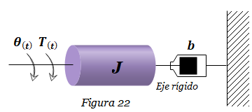
1. Given the System of Figure 22, find the transfer function Θ(s)/T(s).
null

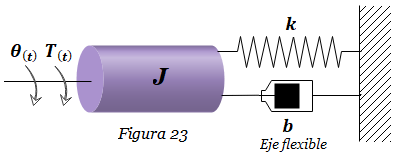
2. Given the System of Figure 23, find the transfer function Θ(s)/T(s).
null

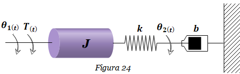
3. Given the System of Figure 24, find the transfer functions Θ1(s)/T(s)  and Θ2(s)/T(s).
null

4. Find the state-space representation of the system of the previous exercise, Figure 24, taking Θ1(t)  as the output and T(t) as the input. Build the block diagram of the system and determine the transfer function Θ1(s)/T(s).

5. Given the System of Figure 26, find the transfer function ΘL(s)/Tm(s).

null

6. Given the System of Figure 27, find the transfer functions Θ1(s)/Tm(s) and Θ2(s)/Tm(s).

null

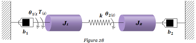
7. Given the System of Figure 28, find the transfer functions Θ1(s)/T(s) and Θ2(s)/T(s).
null

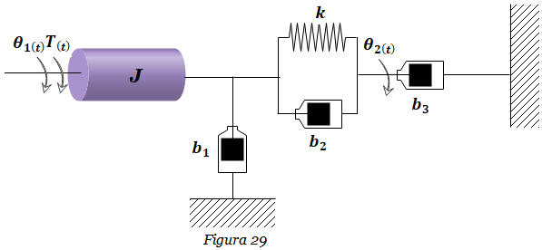
8. Given the System of Figure 29, find the transfer function Θ2(s)/T(s).
null

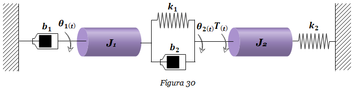
9. Given the System of Figure 30, find the transfer functions  Θ1(s)/T(s) and Θ2(s)/T(s) . Consider: k1=9, k2=3 N-m/rad, b1=8, b2=1 N-m-s/rad, J1=5, J2=3 Kg-m2.
null

10. Find the state-space representation of the system of the previous exercise, Figure 30, taking Θ2(t) as the output and T(t) as the input. Direct Transform the state-space representation obtained into the transfer function Θ2(s)/T(s). Consider k1=9, k2=3 N-m/rad, b1=8, b2=1 N-m-s/rad, J1=5, J2=3 Kg-m2.

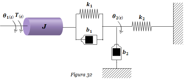
11. Find the state-space representation of the system in Figure 32, taking Θ2(t)  as the output and T(t) as the input. Directly, using Matlab, Transform the state-space representation obtained into the transfer function  Θ2(s)/T(s). Consider k1= k2=1 N-m/rad, b1= b2=1 N-m/rad, J=1 Kg-m2.
null

12. Given the System of Figure 33, find the transfer functions  Θ1(s)/Tm(s) and Θ2(s)/Tm(s).

null

Contact:

  • WhatsApp: +34 633129287
  • dademuchconnection@gmail.com

Immediate attention!!..

Mass-spring-damper rotational system. Problems solved. Catalog 3

In this PDF guide, the Transfer Function of the exercises that are most commonly used in the mass-spring-damper system classes that are in turn part of control systems, signals and systems, analysis of electrical networks with DC motor, is determined. electronic systems in mechatronics, etc. It is a good resource to also learn how to obtain the block diagram of the system, or the representation in state variables. Request via email – WhatsApp

€15,00

You may be also interested in:

Made by Prof. Larry Francis Obando – Technical Specialist – Educational Content Writer – Twitter: @dademuch

Mentoring Académico / Emprendedores / Empresarial

Copywriting, Content Marketing, Tesis, Monografías, Paper Académicos, White Papers (Español – Inglés)

Escuela de Ingeniería Eléctrica de la Universidad Central de Venezuela, UCV CCs

Escuela de Ingeniería Electrónica de la Universidad Simón Bolívar, USB Valle de Sartenejas.

Escuela de Turismo de la Universidad Simón Bolívar, Núcleo Litoral.

Contacto: Jaén – España: Tlf. 633129287

Caracas, Quito, Guayaquil, Lima, México, Bogotá, Cochabamba, Santiago.

WhatsApp: +34 633129287

Twitter: @dademuch

FACEBOOK: DademuchConnection

email: dademuchconnection@gmail.com

Block Diagram, Control System Analysis

Definition of Electromechanical System

«Electromechanical Systems are those hybrid systems of mechanical and electrical variables.» Applications for electromechanical components cover a broad spectrum, from control systems for robots and star-trackers, to household appliances and hard disk position controls on a computer, or the control of DC motors in air conditioning systems for residential installations.

gettyimages-155388818-1024x1024
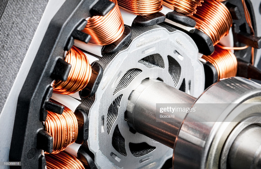
Detail of copper winding, stack and shaft of a electric permeant magnet motor for home appliances.

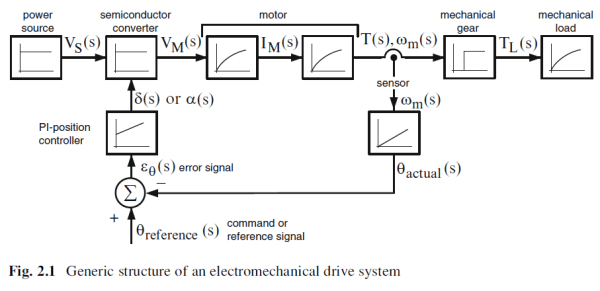
Figure 2.1 shows an electromechanical drive system. It consists of a power and energy source, a gate circuit for the converter, electronic converters (rectifier, inverter, electronic power controller), current sensors (shunts, current transformer, Hall sensor), voltage sensor (divider voltage, potential transformer), speed sensors (tachometers) and displacement sensors (encoders), three-phase rotary machines, gearboxes and specific loads (pump, fan, car, etc.). In Figure 2-1 all components, with the exception of gears, are represented by a Transfer Function (output variables as a function of time), while the gearbox is represented by a Characteristic Function (Xout output variable depending on the input variable Xin)

The electric machine is perhaps the best example of an electromechanical device because of the frequency with which it is used in numerous applications of daily life. An electric machine is a device that can convert mechanical energy into electrical energy (a hydroelectric plant, for example), or convert electrical energy into mechanical energy (a motor).

For the study of electromechanical systems from the point of view of control engineering, we have decided to focus our attention on DC motors, especially armature-controlled DC servo motors, as they are components intensively used in emerging industries that combine electromechanical engineering with Telematics, as is the case with Robotics and Drones technology. And because, precisely, these areas, together with that of electric vehicles and industry 4.0, are initiating a paradigm shift in all areas of life.

null

We are dedicated to developing the mathematical model of an electromechanical system with DC motor, as well as the characteristics of this system when it is part of an open loop or closed loop control system (Servomotors). We also provide numerous examples of how to determine and use the Transfer Function of an electromechanical system to analyze its stability and its response over time (transient and steady state).

And gradually we will cover these industries more specifically, with great potential for innovation and future labor demand.

NEXT:

Sources:

  1. Control Systems Engineering, Nise
  2. Sistemas de Control Automatico Benjamin C Kuo
  3. Modern_Control_Engineering, Ogata 4t
  4. Libro Rashid – Power Electronic Handbook p 663-666
  5. Getty Images

Literature review by:

Prof. Larry Francis Obando – Technical Specialist – Educational Content Writer

WhatsApp:  +34633129287  

Twitter: @dademuch

Copywriting, Content Marketing, Tesis, Monografías, Paper Académicos, White Papers (Español – Inglés)

Escuela de Ingeniería Eléctrica de la Universidad Central de Venezuela, UCV CCs

Escuela de Ingeniería Electrónica de la Universidad Simón Bolívar, USB Valle de Sartenejas.

Escuela de Turismo de la Universidad Simón Bolívar, Núcleo Litoral.

Contacto: España. +34633129287

Caracas, Quito, Guayaquil, Cuenca. 

WhatsApp:  +34633129287   +593998524011  

Twitter: @dademuch

FACEBOOK: DademuchConnection

email: dademuchconnection@gmail.com