Control System Analysis, Electromechanical Systems

Solved Example 2 – Electromechanical system transfer function.

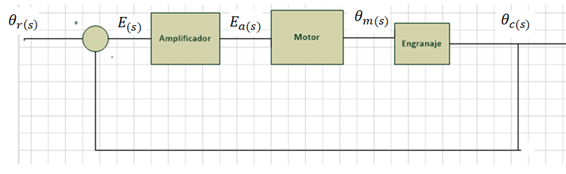
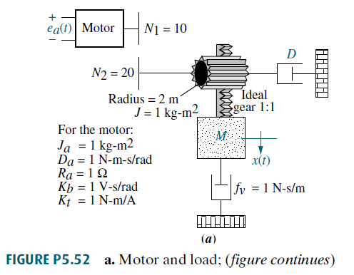
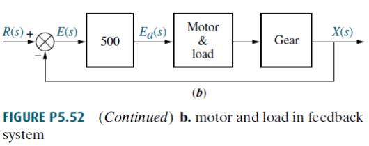
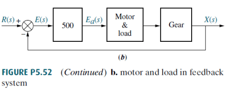
Find in generic terms, the transfer function of the unit feedback system shown in Figure P5.52 (b) of which the electromechanical system of Figure P5.52 (a) is a part.
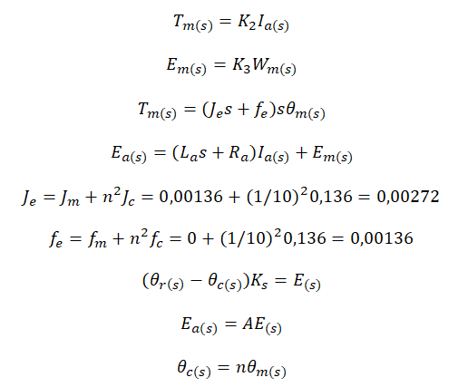
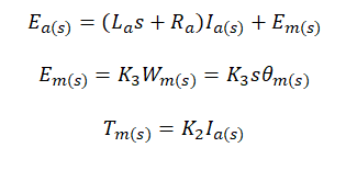
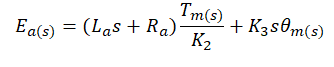
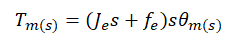
1. System Dynamic
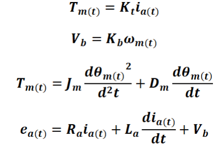
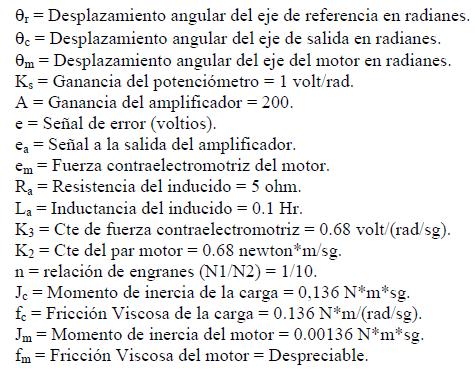
where:
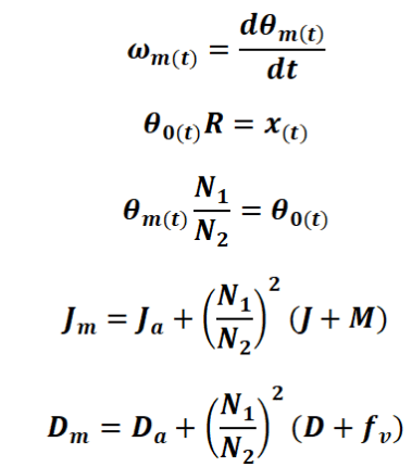
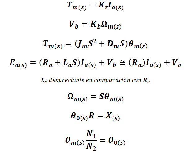
2. Laplace Transform
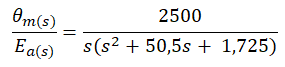
3. Motor&Load Transfer Function (θm(s)/Ea(s))
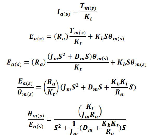
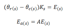
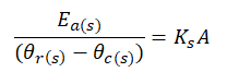
4. Direct Transfer Function

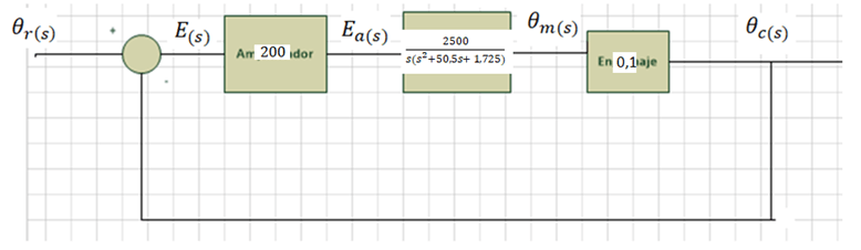
For the system:
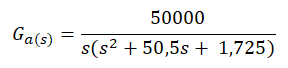
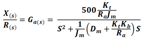
The open-loop transfer function Ga(s) is:
5. Closed-loop transfer function

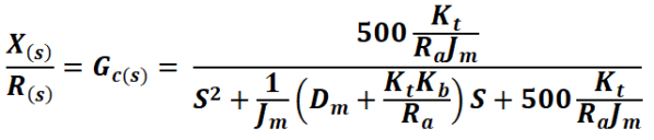
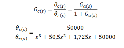
The closed-loop transfer function Gc(s) is:
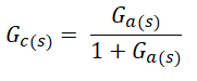
That is to say:

This problem is the first part of one where the transient response is requested so that the overshoot is 20% and the settling time is 2 seconds, see the complete problem in the following link: Example 1 – Transient response of an electromechanical system

Written by Larry Francis Obando – Technical Specialist – Educational Content Writer

Mentoring Academic / Entrepreneur / Business

Copywriting, Content Marketing, White Papers (Spanish – English)

Escuela de Ingeniería Eléctrica de la Universidad Central de Venezuela, CCs.

Escuela de Ingeniería Electrónica de la Universidad Simón Bolívar, Valle de Sartenejas.

Escuela de Turismo de la Universidad Simón Bolívar, Núcleo Litoral.

Contact: Caracas, Quito, Guayaquil, Jaén. telf – +34 633129287

WhatsApp: +34 633129287

email: dademuchconnection@gmail.com
Control System Analysis, Electromechanical Systems

Solved Example 1- Electromechanical System Transfer Function

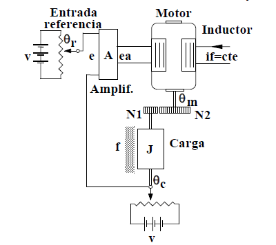
Obtain the mathematical model of the position control system of the figure. Get the block diagram and the ansfer function between the angle of the load and the reference angle θc(s)/θc(s).

null

Data:

null

1. System dynamic

null

2. Laplace Transform

null

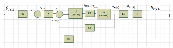
3. Block Diagram

null

Simplifying conveniently to obtain a model whose transfer function is known:

null

4. Transfer function of each block of the previous diagram.

Starting from:

nullWe obtain the following:nullThen, using:null

and substituting, we obtain:

null

Substituting the value of the data in the previous equation, we obtain:

null

Simplifying:null

On the other hand, the gain of the amplifier is obtained using:

null

From where:

null

null

Finally, the gear constant is given by the data and is n = 1/10. We then obtain a block diagram with the following transfer functions:

null

5. System Transfer function.

The open-loop transfer function Ga(s) of the system shown in the previous diagram is:

null

From where we can easily obtain the closed-loop transfer function Gc (s), which is what the statement asked, using the unit feedback:

null

NEXT: Example 2 – Electromechanical system transfer function (English)

Written by: Larry Francis Obando – Technical Specialist – Educational Content Writer.

Mentoring Academic/ Entrepreneurs/ Business.

Copywriting, Content Marketing, White Papers (Spanish– English)

Escuela de Ingeniería Eléctrica de la Universidad Central de Venezuela, Caracas.

Escuela de Ingeniería Electrónica de la Universidad Simón Bolívar, Valle de Sartenejas.

Escuela de Turismo de la Universidad Simón Bolívar, Núcleo Litoral.

Contacto: Caracas, Quito, Guayaquil, Jaén- Telf. +34 633129287

WhatsApp: +34 633129287

+593998524011

email: dademuchconnection@gmail.com